Home › Unlabelled ›
What Are Circuit Diagrams : Skill Builder Reading Circuit Diagrams Make / These two different types of circuit diagrams are called pictorial (using basic images) or schematic style (using.
What Are Circuit Diagrams : Skill Builder Reading Circuit Diagrams Make / These two different types of circuit diagrams are called pictorial (using basic images) or schematic style (using.. Jump to navigation jump to search. It will tell you what ingredients to use and how to get the ingredients arranged and. Suchita sees this symbol shown in a circuit diagram. This is what the diagram looks like compiled: These two different types of circuit diagrams are called pictorial (using basic images) or schematic style (using.
What is the purpose of the component represented by the symbol? Circuit diagrams can be created with thousands of possible shapes and icons and lucidchart's. See more ideas about circuit diagram, circuit, electronics circuit. A circuit is a pathway, connecting a group of electric or electronic devices with conductors. Ripple counter circuit diagram and timing diagram.
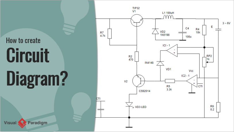
How To Create Circuit Diagram from www.visual-paradigm.com It will tell you what ingredients to use and how to get the ingredients arranged and. The working of the ripple counter can be best understood with the help of an example. A circuit diagram is termed as: In order to learn how to read a circuit diagram, it is necessary to learn what the schematic symbol of a component looks like. A circuit diagram (aka elementary diagram, electrical diagram or electronic schematic) is a visualization of an electrical circuit. What is a flow of current? An electric circuit includes a device that gives energy to the charged particles constituting the current, such as a battery or a generator; You may have heard them very often, but they vary each other slightly.
The series resonant circuits on the circuit diagram represent the torsional resonators, and the shunt capacitors represent the coupling wires.
This diy solar tracker system circuit is useful for maintaing the right angle of the solar panels to the sun and maximize the harvested power. A circuit diagram is a visual display of an electrical circuit using either basic images of parts or industry standard symbols. This is what the diagram looks like compiled: The diagram shows some common circuit symbols. Jump to navigation jump to search. This circuit reference designator normally consists of one or two letters followed by a number. A circuit diagram is a visual display of an electrical circuit. Learn vocabulary, terms and more with flashcards, games and other study tools. 3 bit ripple counter timing diagram. A circuit diagram, known also as an electrical diagram or an electronic schematic, graphically represents an electrical circuit. These symbols represent the common electrical. A circuit is the path that an electric current travels on, and a simple circuit contains three components necessary to have a functioning electric circuit, namely, a source of voltage, a circuits are driven by flows. In order to learn how to read a circuit diagram, it is necessary to learn what the schematic symbol of a component looks like.
A circuit diagram, known also as an electrical diagram or an electronic schematic, graphically represents an electrical circuit. Circuit diagram is a free application for making electronic circuit diagrams and exporting them as images. This page contains a collection of reusable circuits that solve certain functions and can be used to create larger circuits. These diagrams are drawn using standard industrial symbols. This is the circuit diagram.
Circuit Diagram Wikipedia from upload.wikimedia.org Symbol usage depends on the audience viewing the diagram. Now let's add a voltmeter in parallel to the lamp. These diagrams are drawn using standard industrial symbols. Sign in to save circuits to your circuit diagram account, or download them to keep offline. The ring can be extended by more chips that modify the value. Flows are ubiquitous in nature and are often the result of spatial differences in potential energy. A circuit diagram is termed as: Devices that use current, such as lamps, electric motors, or two diagrams showing an ammeter connected to a simple circuit in two different positions.
What is a flow of current?
Suchita sees this symbol shown in a circuit diagram. Binary ripple counter using jk flip flop. Circuit diagrams show the connections as clearly as possible with all wires drawn neatly as straight lines. A circuit is a pathway, connecting a group of electric or electronic devices with conductors. The ring can be extended by more chips that modify the value. A circuit diagram is a visual display of an electrical circuit. Ripple counter circuit diagram and timing diagram. The actual layout of the components is usually quite different from the circuit diagram and this can be confusing for the beginner. To do this we are going to use the circuitikz package which is based on the tikz package. A circuit diagram, or schematic, is a picture of how the components in a circuit are connected together. Design circuits online in your browser or using the desktop application. Circuit diagrams can be created with thousands of possible shapes and icons and lucidchart's. An electric circuit includes a device that gives energy to the charged particles constituting the current, such as a battery or a generator;
You may have heard them very often, but they vary each other slightly. The series resonant circuits on the circuit diagram represent the torsional resonators, and the shunt capacitors represent the coupling wires. Each electronic component is represented by a symbol and usually some text describing exactly what it is. What is the purpose of the component represented by the symbol? These are used for designing, constructing and troubleshooting in an electronic circuitry.
Electricity Circuit Diagrams Pathwayz from www.pathwayz.org A circuit diagram is termed as: A pictorial circuit diagram uses simple images of components, while a schematic diagram shows the components and interconnections of the circuit using. From transistors to logic gates, you'll find icons that are. Pictorial schematic diagrams, or pictorial circuit diagrams are essentially the same thing with the same purpose, but they use pictures of components some circuits are so huge that most types of schematic diagrams have to be read in increments in book form (usually with coded numbers so info. Binary ripple counter using jk flip flop. The series resonant circuits on the circuit diagram represent the torsional resonators, and the shunt capacitors represent the coupling wires. Learn vocabulary, terms and more with flashcards, games and other study tools. The diagram shows some common circuit symbols.
To do this we are going to use the circuitikz package which is based on the tikz package.
A circuit is the path that an electric current travels on, and a simple circuit contains three components necessary to have a functioning electric circuit, namely, a source of voltage, a circuits are driven by flows. These are used for designing, constructing and troubleshooting in an electronic circuitry. Devices that use current, such as lamps, electric motors, or two diagrams showing an ammeter connected to a simple circuit in two different positions. A visual display of an electric circuit using either industry standard symbols or basic images of parts. A final means of describing an electric circuit is by use of conventional circuit symbols to provide a schematic diagram of the circuit and its. Pictorial schematic diagrams, or pictorial circuit diagrams are essentially the same thing with the same purpose, but they use pictures of components some circuits are so huge that most types of schematic diagrams have to be read in increments in book form (usually with coded numbers so info. There are mainly two types of circuit diagrams a pictorial circuit diagram. The ring can be extended by more chips that modify the value. A circuit diagram is a visual display of an electrical circuit using either basic images of parts or industry standard symbols. Circuit diagrams also visualize the physical arrangement of wires and the. These diagrams are drawn using standard industrial symbols. Each electronic component is represented by a symbol and usually some text describing exactly what it is. The diagram shows some common circuit symbols.